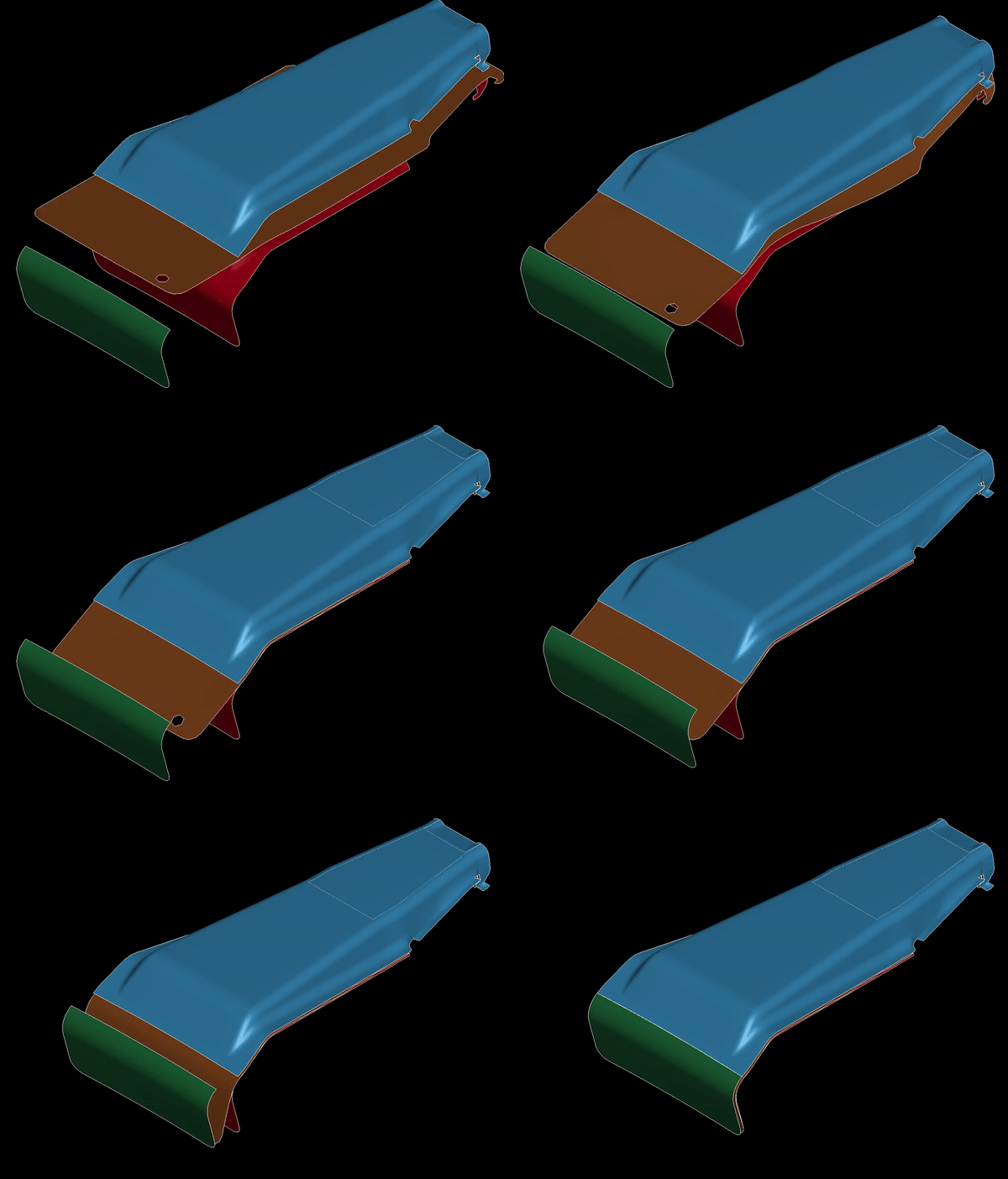
A student project conducted by George Arikupuram, Nishank Deviah, Biwang Jiang in 2023.
In the course Digitalization and Automation in Engineering Processes the students get to work with automation of engineering tasks and learn concepts from AI and design automation to facilitate the development of product platforms and mass customized products.
These images show the results of a project in collaboration with Thule. The task was to automate the process of simulating the forming process of a mounting bracket for a roof rack. Each bracket is customized to every car model which makes the process recurring for each new car model on the market.
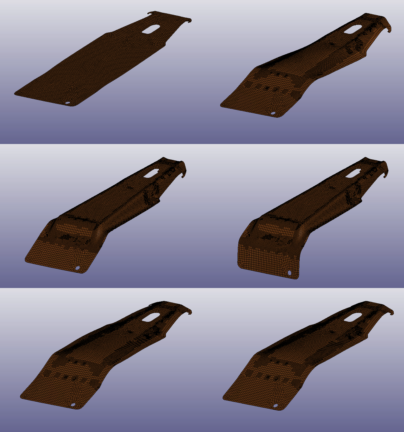
For some components which are high in variety but share many common design features it is of interest to create a system for automatic product compliance evaluation. In this case this means evaluating the ability to form the sheet metal without generating strains that would risk cracks in the sheet metal. Such evaluations require the setup of tool surfaces (punch, die, blank holder) as well as a blank. The blank needs to be a flat "unfolded" surface. These surfaces are then meshed. Loads are imposed on the meshed surfaces and an explicit simulation is conducted using LS-Dyna to generate the deformed shape and the resulting strain field which is used to gauge if there exists risks for cracks.
The students had to identify which engineering processes were reoccurring and simple enough to be somewhat easy to automate by scripting the design process as well as the computation setup process.

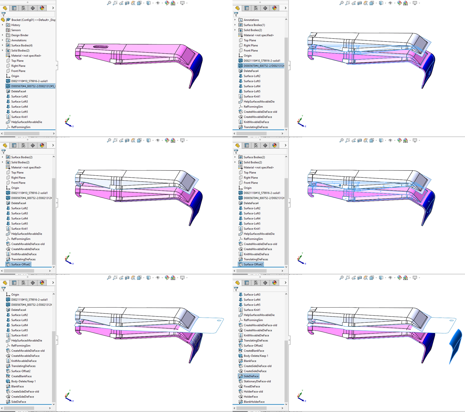
SolidWorks API programming using C# was utilized in order to automate the generation of tool surfaces (the die, punch and bland holder) from the solid brackets as well as the unfolding of the blank surface.
Common design features where identified, in this case the location of the big hole cutout, and the need for an extra side tool. The hole was used to define a coordinate system which is used to orient the brackets. It is the vast amount of geometrical features which make any automation of design tasks a non-trivial matter. For some cases, design rules need to be established and clearly communicated to the design team for the automated evaluation system to work. This is of course not desired since it hinders the creativity of designers and should be avoided by making the automated design algorithm handle these cases. This is a very time consuming and hard task. For this project, some assumptions for the source CAD were needed to be made.


Python programming was used to automate the pre-processing by generating input-files using LS-PrePost.

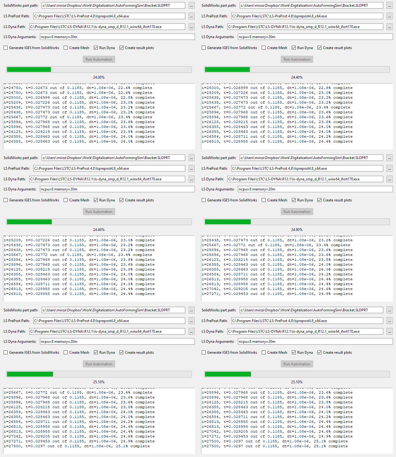
A graphical user interface was created in python for easier usage, thus the generation of results for a forming simulation is now just a button press away. The intended user is a design engineer who wants to evaluate if the design is good or not by just running the automated forming simulation and using a SolidWorks part as an input. All the knowledge of computational mechanics, sheet metal material modeling and load cases are confined to a input file which is tested and validated by the test and simulation department.
The design engineer is now able to quickly evaluate different designs in terms of manufacturability.

The code repository can be found at: https://jthgit.hj.se/compmech/autoformingsim.
Automated evaluation systems like this could in the future be used with optimization algorithms in order to create better and more sustainable product components.